What does an IMU consists of?
An IMU comprises three major components:
- Accelerometer
- Gyroscope
- Magnetometer
Each serves a specific purpose. To simplify, I’ll use the ICM-20948 IMU I’ve been working with to explain the function of each component. You can find the datasheet here
Note: This link might change with updates. Feel free to comment here, and I’ll update the blog.
Accelerometer

Starting with the easiest component to understand, an accelerometer has mass that squeezes a piezoelectric material which in turn produces a charge proportional to the force. How? That will require a deeper dive into electronics.
The IMU gives acceleration in terms of F=mg that is 1g,-2g etc. The information about the range will be given in the data sheet for example for ICM-20948 following ranges are possible 2g, ±4g, ±8g, and
±16g.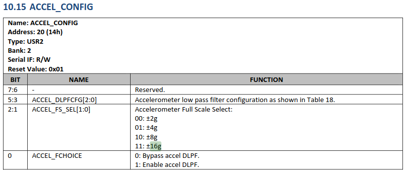
You can select the desired range by saving a hexadecimal value inside the given register. We will see how to use these registers in upcoming blogs.
The Accelerometer will give you information on all three axes viz. X, Y and Z. Different IMUs store this information differently. For ICM-20948 here is how the information is stored in its registers.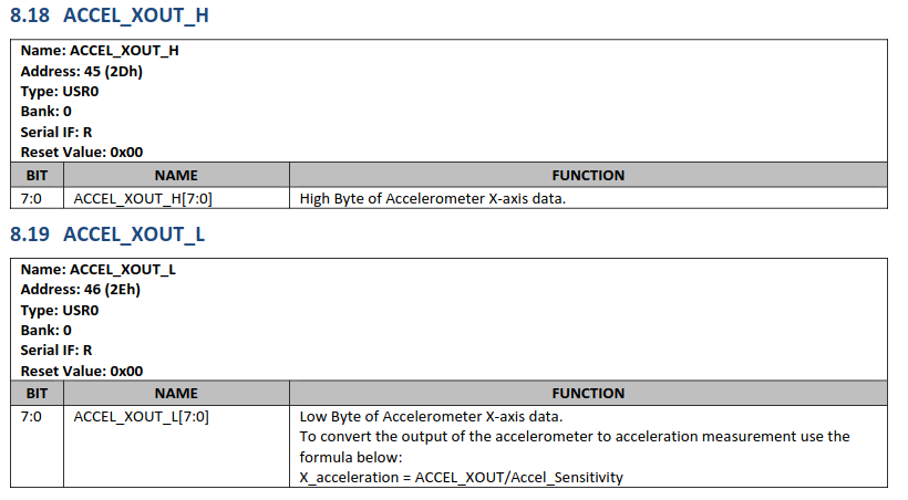
A register can only store 8 bits but acceleration is stored in 16 bits thus we need two registers to get information about one particular axis.
We will see why this is the case and how to read values soon. I pinky promise.
Acceleration gives us information on the movement of the object in one direction. We have information about 3-DOF which is three degrees of freedom. Good but what about the other three, rotations? This is where a gyroscope comes into the picture.
Gyroscope

A gyroscope provides the rate of rotation and angular position. How does it work though?
It is measured by fetching the value of Coriolis force. There are two masses suspended and they move in opposite directions. When a rotation is applied one mass moves up while the other mass moves down as seen in the animation.
The difference in the forces helps to calculate the angular velocity.
The information is stored similarly to the acceleration values. The registers have the following ranges ±250 dps, ±500 dps, ±1000 dps, and ±2000 dps. dps represents degrees per second.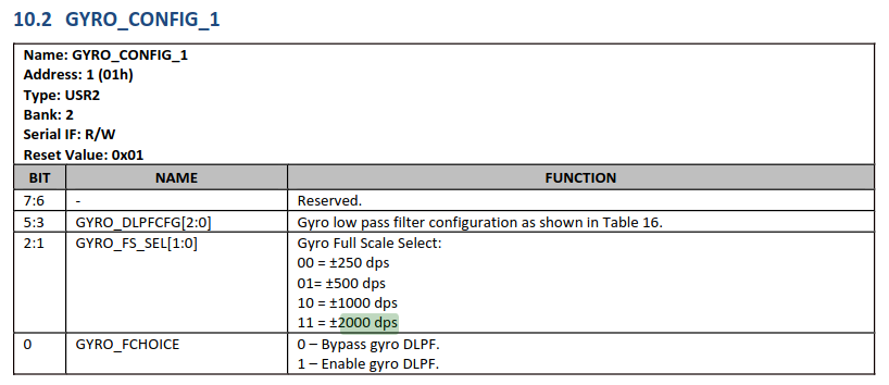
The gyroscope stores the values of the rotation of the X, Y and Z axes in the same 16-bit format.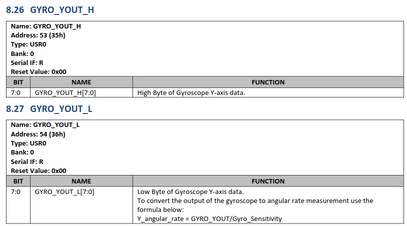
You must have observed the term Gyro_Sensitivity. We will talk about this term when we are coding the driver for this IMU.
Magnetometer

Wait how did this new component come into the picture. Don’t we have everything to get started? What else are we missing?
The information from Magnetometer is very specific to certain algorithms. Gyroscopes have something called zero drift. As the name suggests even when the IMU is stable one can observe a non-zero reading from gyroscopes and it can get worse over time. For Roll and Pitch zero drift can be eliminated by Accelerometer measurements. However, we need a Magnetometer to eliminate the zero drift in Yaw.
Magnetometer works on the concept of the hall effect where the particle is moved mechanically inside a coil using a piezoelectric actuator making electric current. A change in magnetic field causes a change in current.
Our ICM gives us the range of ±4900 μT, and T represents Tesla the unit for magnetic flux.
The register map is a bit different since the magnetometer is a different chip.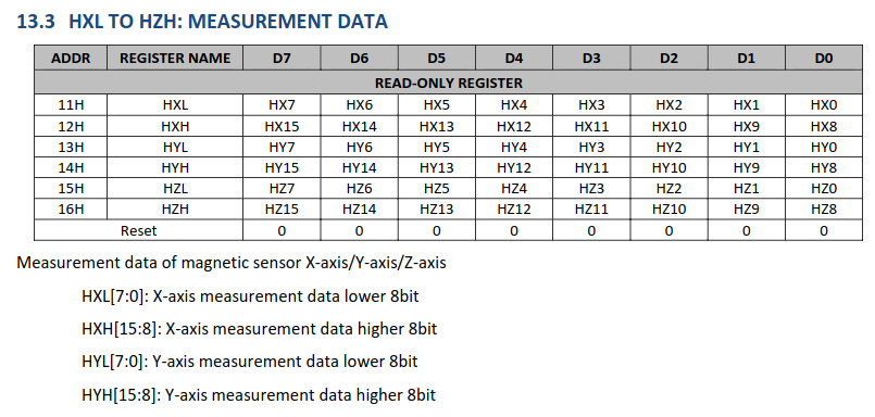
What is next?
Okay so now that we know what each component does we can start writing the driver and after that, we will use IMU on a robot! How awesome is that!